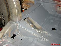
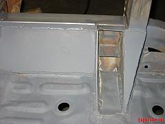
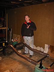
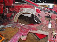
The rear frame was a weekend project, no doubt about that. Mark and I actually did a really good job of knocking out a bunch of work that weekend – we completely cut out the old rear frame, prepared the car to receive the new frame, and then welded the new frame into the car. It was nuts 😮 We went through countless blades on all of the cutting tools we used – the Sawzall, an air powered body saw, an air powered die grinder with cutting discs, and a cheapie 4″ angle grinder. All that stuff was used to break through a lot of the stock factory sheetmetal. I had always had the impression that these cars were tough, and that was reinforced that weekend – the stock factory crossmember and subframe are up to six layers in some places! In order to grapht the new frame into the old body, we had to weld the new frame into existing factory steel – and we wanted it to be strong – that part was very important. So, we basically projected a plane onto the factory steel where we wanted to put the new frame, and then cut on that line. Lasers are awesome 🙂 We basically created a ledge to sit the new crossmember on, that existed on top of the factory framerails. It was a challenge cutting the ledge, but only because that part of the stock framerails ends up being every which way but straight. So, we managed a reasonable facsimile of an L on the stock factory steel, and then set the new crossmember on top of it. At the end of the day, after getting it all tacked up – it was all square, straight, and level – imagine that 😀 After that, we spent a considerable amount of time reinfocing the stock steel so that the rear frame would be well supported. We made some 1/8″ steel plates that we welded to the stock framerails, that also welded to the new crossmember to give it a lot more rigidity, and to help the cute thin factory steel support the weight of the crossmember. When we were done, it all came out really well, and the crossmember was firmly planted in the car. What we did would have easily been sufficient to just weld into a street car, and go. Solid!
Author Archive: FasterThanYou
The Intake Manifold

The runner halves, all TIG’d up, ready to be cut

The runners all trimmed up, complete with taper

Mark HNC’ing up the manifold flange

The manifold, tacked together

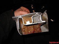
4g63 Intake Manifold Flange, Completed.

The completed RWD intake manifold.
Mark and I spent the weekend of the fourth of July 2004 making the sheetmetal intake manifold on the rear drive. What’d we start out with? A four foot by eight foot sheet of 4043 (.090″) and a chunk of 6061 for the flanges. I think the 6061 was 1/2″ thick, but I could be wrong. Well, that stuff, and a lot of Mountain Dew Livewire. We’re addicted. That stuff is way too sweet – we call it “nectar”.
The plan went something like this: I was to do all the sheetmetal work and welding, and Mark was to Hessler Numerically Control up the flanges for the manifold. For those of you who don’t know, Mark is a geek – sometimes it’s a little scary. The flange he HNC’d was accurate to a few thousandths. It fit the head perfectly.
So, Mark plotted out the flange, and I got to work
While he was doing that, I started shearing up the sheet aluminum. Then I made up eight runner halves to weld up to make the runners. After breaking the runner halves, I sheared them to length, and welded them up.
So, I did all that, and Mark was about halfway done with the flange.
Next was the plenum. I’ve got a roll, but it sucks ass, so after struggling with it for about an hour, I resorted to using a heavy duty set of gloves, some muscle, and cursing. A vice helped me out a little bit too. The problem was that the plenum is .090″ and the roll I was using is only designed for like 20 gauge steel – (.036″) so it really wasn’t meant for the job. Lesson learned. After finishing that up, I laid out the rest of the pieces for the plenum, trimmed up the runners, the main part of the plenum, and started getting anxious, so I laid out the oil pan on paper.
When Mark completed the flange, it was time to get welding. I welded the runners to the flange first, and then tacked everything else together.
After that, I welded it up
Mark started the throttle body flange while I was doing all that stuff. When I was done welding the plenum to the runners, I cut up some 6061 to tap for bungs on the underside of the manifold, and welded it onto the plenum.
Mark completed the Throttle body flange, and then worked the throttle body over a little with the mill to clean it up while I welded the throttle body flange to the plenum.
Why build a RWD Eagle Talon
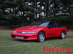
Why would I want to make a rear drive Talon? Simple – I like racing, I want to go fast, and I do not want to deal with driveline problems. The stock configuration for this car was 195 horsepower, at the crank. That’s roughly 150-ish to the wheels. Last time I was on the dyno in AWD form, it laid down 485 horsepower, and 360 lb/feet of torque. Best ever on the dyno when it was AWD? 491whp. Transmissions, axles, cluthes, propeller shafts, and other parts designed for 195 horsepower don’t typically like taking almost three times the power they were designed to handle. Something’s got to give. So, for the longest time, I just used “street” tires so that something had the opportunity to give. Well, if you’re not getting traction, you’re not going fast enough. The car went 11.18@132.84mph. 130+ is mid 10 second territory, but I wasn’t able to run a 10 second pass. I certainly wasn’t able to drive the piss out of the car, either. I ended up bummed out. Upgrading to something else stock would just be expensive, and I’d still be able to break things I didn’t want to break. On the other hand, I also pondered – I have always wanted a “race car” – the 4g63 has ample power to run 8’s with the right tuning, so as long as I can get the power to the ground, and not have to worry about chassis, suspension, or drivetrain, then I should be all set, right? Okay, so simple, make a rear drive, right? Okay, that’s also not the full reason. I also always wanted something I could bolt monster slicks up to, and just go hammering down the 1/4 mile every weekend in the summer. Something fast, something that showed that skill was put into it, extra ordinary, and something that would piss people off. Okay, so I have a mean streak 😉 I love reeling in big blocks. I like it even more when they think they’re going to catch me on the big end, and don’t. The last trip to the track, I had a LOT of people who normally wouldn’t look twice at an import come up to me and ask questions about the car. I was over a second faster than any other import in the joint, and had 12 mph on the second closest import. Shit, I was running the same kind of MPH that the 10.5″ slick cars were running 🙂 Okay, so those aren’t all the reasons. The last one? Because I can 🙂 That’s not meant to be snooty, it’s just me showing my determination. Have you seen some of the cool things Mark Hessler, Rick Garnaat, Jay Danhof, and I have created? It’s just cool. You should see the “shop” we build this stuff in. It’s a regular two car garage. Yeah, we’re cool like that 🙂 Oh, I’m kind of stubborn sometimes, too. It happens. In addition to that, I’m all about working on stuff like this for fun. It’s a hobby; a passion. It’s what I like. If I had a dream job, it would be building race cars.
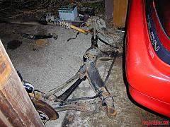
Rear Axle Mockup

The mocked up axle in the car

A view of the slicks mounted up on the mock axle
The rear axle of the Talon Wasn’t very hard to mock-up. The four-link bracketry had three inch holes in the middle of the four identical brackets for an axle tube. Well, as luck would have it, I had a three inch exhaust on the Talon previously that I had taken out of the car. The exhaust was getting pretty rough, being about five years old, so it wasn’t going to be going back on this Talon, or any DSM anyway. I broke out the Sawzall, and went to town on a large straight piece of former-exhaust-pipe. After I got that squared away, I took the four-link brackets, and persuaded them onto the mock-up axle. After that, we welded some flimsy little hubs onto it, complete with three bolts on each to hold the new wheels and slicks, and then placed it all in the car where we wanted the wheels to ultimately sit. Why’d we do this, instead of using a real axle? Weight and width. The real axle weighs considerably more than the mock up axle did, and would be a bit more unruly to work with trying to mock the rear suspension dimensions. That, and we didn’t have an axle to work with at the time. In addition to that stuff, we didn’t yet know how wide the axle needed to be, and a full width axle would have been far too wide.
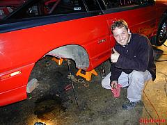
Removing Old Components
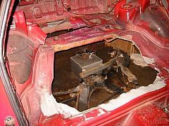
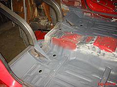
There was a lot of stuff in the car that needed to be removed. Most of it was originally permanent. Back in 2001, my father and I installed a mild steel roll cage – it was a five-point, and was pretty beastly. The cage rested on top of the stock factory equivalent to what you’d consider to be the crossmember on a car with a frame. In the Talon, it’s the front most part of the rear seat. In any case, this part (and the rollcage, because it was mounted there) had to be removed in order to install the new rear frame. The other thing that had to be removed was the floorpan – I don’t know about you, but I had never removed a floorpan from a unibody car before. So, how would I go about doing that? Saw-zall. 🙂 It worked great. I purchased a saw-zall a few years ago for various Talon projects, and it totally fit the bill. I also had an angle grinder and some cutting discs for it that worked where I couldn’t put the Saw-zall. In any case, I went to town tearing both the rollcage, and the floorpan out of the rear part of the car.
It was a very good learning experience. Now I know why these cars weigh what they do from the factory (they’re 3100-ish pounds) – there are layers upon layers of steel in the car that I didn’t know about. Everything was spot welded – everywhere. It took a long time to really get the ass end of the car cleaned up to the point where it was just down to some framerail, and a little bit of floorpan welded to the framerails. When that happened, though, then it hit me. This frame is holding *everthing* up. Cutting the frame out would severely compromise the rest of the rear end of the car. So, how would I support the ass end in multiple locations while this thing was being disassembled?
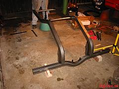
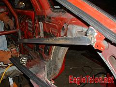
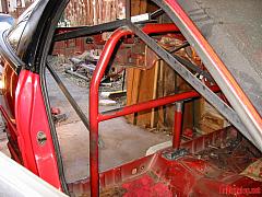
Well, that roll cage really came in handy. I took the cage, welded it back in the car about a foot forward of the location it was in, and then triangulated everything in the back of the car to the cage to support everything. Yes, it sounds ghetto. Yes, it worked very well, so shaddup 😉 I don’t see *you* building a rear drive 😮 Once I was sufficiently satisfied with the bracing in the back of the Talon, I cut the frame out from under the new angle iron jungle gym. The frame came out easily, and without incident. Cake, right?
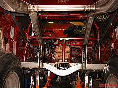
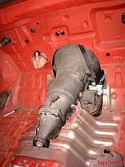
Turning the Engine
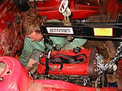
Crawling around in the engine bay
Oh no, someone gave Mark a body saw!
TH350, meet the Talon
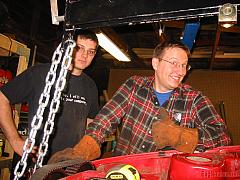
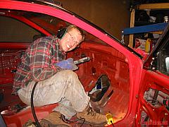
Rick and Mark hanging out
Turning the engine sideways so that we’d be able to get the power to the rear wheels wasn’t too big an ordeal, but it was something that was a bit errie. I mean here I’ve got this car, my car, and I’m cutting the shit out of it. It just didn’t seem right at times, but it was still amusing. Most of the time I wasn’t too freaked out by actually cutting up the car – My general thought was “Eh, it’s just steel, I can weld more abck in if I need to.” We weren’t quite sure which transmission to use – Mark was all about a transmission with a lockup convertor, and I wanted to use a TH350 or TH400. I was more about the TH400, but talking to some Chevy guys, learned that the TH350, if built well, would handle all the torque I could throw at it. Through a friend, I picked up a TH350 on trade for some other work. It was cheap, and even if I didn’t end up using it, I would still be able to use it for mockup purposes. The TH400 would potentially be a little longer, but the TH350 worked for now. Here’s the cool thing: The way the rear crossmember, and the rear differential sat in the car, we would have a 0 degree angle on the pinion, and a 0 degree angle on the transmission… but only if we used mounted the engine in the car ~4″ lower than it was previously. Was that even possible? Well, not with the stock oil pan, but that’s okay, because the stock pan had to go. What’s even better is that the stock cam gears cleared the hood, so we wouldn’t even have to cut up the hood, or install a cowl or anything like that. It’d sit tightly under the factory steel, with a little room to spare. In addition to that, the ass end of the car was also spec’d out to sit at stock right height, even though the new slicks were 29.5″ tall, ~6″ taller than the stock tires on the car. All this is in fact intertwined with how we’d turn the engine 90 degrees, so that it sat “right” in the engine bay, in V-8 terms, anyway. We needed to make sure we had room, the engine could sit level, center, and square in the car. So, all those other things I just mentioned played a large factor in that. Once we did all that, we had the engine and transmission on a hoist, ready to weld in place. So, it was time to figure out mounting locations. The engine plate would end up being the mid-mount for the engine / transmission, with a bar going across the front for a front engine mount, and a bar going under the tailshaft of the transmission as the rear engine mount. Now, mind you, this was a good chunk of the weight of the car. Altogether, this stuff probably weighed in excess of 500 pounds. In addition to that, the engine was expected to make torque like whoa, so It’d need to be able to handle that. So, since the mid plate was so hefty, we decided to use that as the main engine mount. We welded tabs to the midplate so that the entire assembly would bolt up to the engine mounts without an issue. After that, we constructed some solid mounts out of some 1/8″ 1018 mild steel. They’re solid! We cut and welded the main pieces of steel for the mid mount, and then created the chromoly front engine mount, and rear engine mount, also out of chromoly tubing. That stuff is 1-1/4″ .065″ wall, I think (It’s been a while.) After that, we finished up the mid mounts by boxing them in, and painted them up for a nice finish 🙂
Where To Begin?
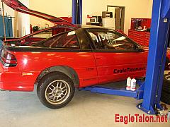
On the lift at VT Competition Engine Development
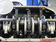
The 2.3 Liter Stroker
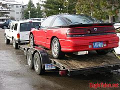
Loaded up and ready to race.
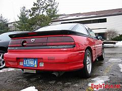
Waiting for the snow to melt
So, Where do you begin with a project like this? At the beginning, of course 😉 Seriously, though – you begin at Outback on a cold winter night with a good friend (Mark Hessler, in my case) that’s willing to prod you in the ass to get things moving. I was waffling about what to do to the car next. TRE Transmission? Magnus Dogbox? Even with those options, I wouldn’t be comfortable with the breakage that I think I’d end up with. Okay, what other alternatives? ‘Change the driveline completely’ was the only other one that came to mind. I remember the first year Dave Buschur had his RWD first gen at the shootout. I loved the matte black look that the car had, but even more so, I liked that dave had back-halved the car. Since then, I’ve wanted a RWD Talon. So, that was about it. I brought it up to Mark, he replied with “make it rear wheel drive” and, after some waffling, decided to go for it. Cake. Alright, not so simple. It was about like that, and then the napkin drawing started. We started pondering exactly what would be required to actually produce this new chassis, and then to get the engine turned the right way, and then get everything else squared away. We asked ourselves some questions like “what are the goals for the car?” and “can I live off Ramen noodles for a year?” … you know, the important stuff. After deciding that I didn’t need the money anyway, we got down to business. What were the goals for the car? Power? Configuration? What would we use to accomplish these goals? Would we be able to take on a project like this? How long would it take? Goals for the car? 8.50’s. On a 10.5″ tire. Power?: 850 horse. It’d be nice to have that to the wheels, but there are some power hungry components. Well, I really mean there’s a convertor with lots of loss. So, I’m okay if it’ll whip out 850 at the crank. That should be close to 8.50’s if there isn’t too much loss in the convertor. Configuration? Yeah, RWD. We’re using a Chevy 10 bolt rear end, stuffed with lots of racing goodies 🙂 Accomplishing these goals? Time, Money, the ability to fabricate, and the dedication to getting it done. We are working on all those things as we build the car 😉 Taking on a project like this? Looking back, even though I didn’t consider myself naive then, I still didn’t know it would take quite as much of everything that it has. How long will it take? We’re about a year into it. I’m sure it’d already be done, had we kept the pace that we did up for six months. That just isn’t possible, though. Mark and I typically spent 30 hours a week on the car, in addition to having full-time jobs. It gets old after six months, no matter how “worth it” it is.
You must be logged in to post a comment.