Okay, so some of the things I’m going to talk about are a little bit overdue. First, I went around the car the other night and snapped a few pictures of things that I may have done a long time ago, but didn’t really cover very well, or that you’ve never seen a picture of. Anyway, the following are a bunch of pictures and explanations – click on a picture for a fullsize view:
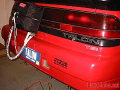
A guy who lives here in Howell, Matt (One of the only active participants of the Eagletalon.net messageboard too 😉 ,) mentioned that the back of the car looked a strange not having any taillights, and asked what I was planning on putting back there.
The plan has always been to put the stock taillights in the back of the car, and I even went as far as putting the rear end of the car together at one point in time. But for some reason, I had never taken a picture of it all together. So, there it is. 🙂
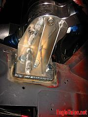
I also hadn’t actually taken any pictures the water pump and water pump bracket. The water pump is in relatively the same spot as the stock factory aircan, if you can imagine that. It’s a CSR racing electic pump, mounted to an aluminum bracket that I wanted to make sure was nice and beefy. And, well, it is. I can stand on it. And it’s light. It’s amazing how strong you can make things. And actually, now that the water pump has power to it, the water pump bracket is probably way overkill, but I would rather have it be light, strong, and never have to worry about it. And It’s mounted to the framerail on a series of bolts that’ve been mounted in the framerail. You can see that I actually took a sheet of 1/8″ steel and welded that to the framerail. Again, this is probably all overkill, but it works well.
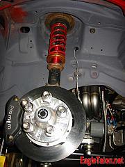
The other thing I haven’t really shot any pictures of is the front strut assembly. Now, the pictures that I have now aren’t the final version of the assembly – I actually have to replace the upper mount with a set of billet aluminum mounts that I got from Ty at RRE, and I also have a new set of Koni struts, and strut bodies that will be all cleaned up and on the car. Basically, all the rusty shit in the next picture will be replaced 😉 In the background, you can see the -4AN turbo oil feed line, the -4AN oil pressure gauge line, and the -8AN turbo turbo line. You can also see the sweet ass header (ahh, modesty ;-p) Plus, the big cool damn Wilwood dynalite front brake kit.
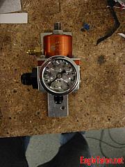
The next item on the list is something I actually finished up this week. Tuesday night, I finally put together a drill press that I got for Christmas. I guess it was only a matter of time before my Dad wanted his borrowed drill press back, but it [i]was[/i] nice of him to get me one of my own for Christmas. this post isn’t about that though 😉 It’s about what I did with it. I took my SX Fuel pressure regulator, and finally made it AN Compliant. The SX regulator, by default, has an 1/8″ barb on the side of is for the vacuum port. You hook that up to your intake manifold, and that’s the vacuum / boost reference. All the other holes machined into the FPR are either 1/8″ NPT or AN Port. And, my master plan is to have all the plumbing on the car to be AN – So, the FPR needed to be modified. I drilled out the 1/8″ barb, and tapped a 1/16″ NPT hole into it. I got a 1/16″ NPT to 4AN adapter fitting, and threaded it in. So now, it’s all set, and most of my plumbing is set. I still have to figure out the Wastegate setup, but almost all of the vacuum and oil pressure lines on the car are now AN.
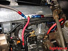
And, this is the rats nest of a wiring harness. In this picture, you can see the bottom of the intake manifold, which is where all the plumbing and wiring for the engine is hidden. The wiring is okay – most of it has been tested, and all I need to do is find a way to mount it to the intake manifold – no big deal. The main trunk sort of has all these things coming off it. I’ve spent a lot of time making it as tidy as I felt I could. Anyway, you can also see the aluminum mounted on the side of the engine – that has the MAP sensor and the two mitsubishi power transistor units mounted to it. They’re wired into the Haltech harness, and determine when the COP ignition is fired. The car has two Power trasistor units because each unit contains two transistors – and instead of hooking them up in parallel, I wanted the coils to have their own ignitors. The “proper” way to do this is really to run a CDI ignition box, but I want to see if this can work because it’s a more simple solution. I guess we’ll see 😉 In this picture, you can also see all the mad AN plumbing action, with the exception of the MAP sensor. It’s a standard GM 3 bar map, so it has a 1/4″ barb fitting on it, with no option of anything that I can convert to AN. So, until I upgrade to something like an AEM 3.5 bar sensor, this is just going to be the setup. I guess I can live with it. You’ll also see the 2 gauge wiring going to the starter. And, the alternator is also hooked up. I actually managed to use the stock alternator plug connector, and was able to remove and replace the stock spade connectors in it with new locking spade connectors that also work with my modular relays that I’m using in other areas of the car.
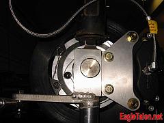
Ugh – okay, carpel-tunnel setting in ;-o Last but not least is a picture of the back of the front upright setup. About 14 months ago, we finished this project up, but aside from some pictures of the front uprights bare, I had never really posted a picture of the whole assembly. Well, here you can see it. The upright has the Chromoly kingpins, which is what the Wilwood brakes connect to. And, as you can see, the Wilwood has been all safety wired so that none of those Really Important brake bolts will come loose. Also, you can see the steering arm welded to the rest of the upright, along with the spacer underneath. All of these have been designed to minimize bump-steer, which is generally considered to be something somewhat misunderstood by a lot of people. Anyway, you can also see all the grade 8 hardware mounting the Wilwood caliper to the upright. And, of course, the 3AN teflon lined brake lines. “For offroad use only” 🙂

