Spring 2010 Updates

I’ve been working on getting things tidied up for the start of the season – lots of random stuff has been going on, so I thought I’d share a quick overview of some of the things I have going on right now:

My Driveshaft Sensor

My Driveshaft Sensor

The new Haltech is almost all buttoned up – I just need to make a mount for it – that should only take a little bit to actually do; I just have to do it already.

I have a new driveshaft speed sensor – this will be used for both the Haltech and the Logger that I’ve made. The sensor is simply a magnetic pickup sensor – it’s actually the same sensor that the Haltech would use for a crank trigger, except that it’s been re-purposed by mounting to the rear differential on the car. My part on this has pretty much been buttoned up – I weldedย  a bracket to the diff, and mounted the sensor to the bracket. The only thing left is getting the yoke collar made, and I’m waiting on my dad for that since I don’t have a lathe.

I also worked on beefing up the 4-link brackets. The original brackets are simply some 3/16″ plate steel welded to the differential – I had always planned on boxing them but hadn’t gotten around to it – I had actually kind of forgotten about it until last year. So, since the car was down for a bit and I was already welding on the rear differential I decided that now was the time to finish this part up. So, I took some 1/8″ plate and cut and bent it into a shape that closely resembled the shape of the existing 4-link brackets. Then, I took turns tacking it into place with my torch and massaging it into a close fitting shape with my sledge hammer.

4-link bracket being boxed - this was taken during welding

4-link bracket being boxed – this was taken during welding

The picture to the left is what the driver’s side bracket looks like – this was taken while I was welding it up – the end result is completely welded on both sides, so it’s as sturdy as it can be now. This really beefed up these two brackets – they’re just freaking solid now. It actually took me a while to do these, although they look relatively simple. The differential soaked up an amazing amount of heat – while welding it, the brackets really didn’t get even hot to the touch, but I took precautions and pulled the teflon-lined rod ends out of the differential while weldingย  near them. The rod ends are pretty expensive, and being lazy is not a good excuse to have to replace them – they should last a long long time.

Once that was done, I was able to paint these brackets back up to protect them and get holes drilled to re-mount the brake lines. Once completed, Rick came over and helped me bleed the brakes and get a few other things on the car buttoned up.

Oh, yeah, I also replaced the wheel studs on the rear of the car – I had never really liked the studs that were on there, and the new ones were about 1/4″ longer. They look nicer, too – I’m kind of sick of looking at rusting black-oxide coated hardware ๐Ÿ˜‰

After that, I spent a lot of time measuring up valve heights and head stuff. I’m working on getting a new set of cams in the car. Basically, I want the largest cams that will fit, but I’m finding that I’m going to have a difficult time getting really big cams in there. Kevin Kwiatkowski helped me out a ton with all the valve information – I provided him with numbers and he provided me with lots of information about different cams. Kevin is crazy, but in a fantastically delicious sort of way ๐Ÿ™‚ Anyway, the end result is that I have a set of cams waiting to go in the car, but I need to upgrade the springs that I have first or I will end up facing some valve-float, and I don’t want that. So, I’m working on that right now, and hopefully will have that issue cleared up soon.

I have also been doing some other random things in order to get ready for the season – making plans and the like. I want to get some sort of notification list or something going because people always ask me what events I’m going to, or ask me to let them know when I am planning on making it out to the track. Unfortunately, it’s hard to stop on a race day and say “George, Bill, Bob, Harry and Mike want to know that I’m going to the track – I better spend the next hour on the phone” – those are all fictitious names, but you get the idea…

Spring 2008 Updates

It’s been a long long time since I updated this page. I apologize ๐Ÿ™‚ As is the case, life takes precedence every once in a while and those issues end up being more important than updating a website about a car, no matter how cool the car is. So, until I’m independently wealthy, I have to fit in updating the site when I’m not doing normal things required for life, or working the the car that this site is all about.

Speaking of the site, I have a lot of things swirling around in my head about what I want to do with it – I want to redesign it soon, but I don’t quite have it set in my head, and I don’t have the time to redesign it yet, so it will probably be like this for a bit longer. It hasn’t hurt yet…

Oiling

You probably want to know what’s happening on the *car*, don’t you? Okay, I’ll get to that. Over the past four or five months, I’ve been doing a lot of random work on the car. There are hundreds of tiny projects, from making brackets to getting the rear tinwork finished up. And this is all I’ve been spending time on.

This series of events is in no particular order:

GT4202 covered in oil.

A lot of oil on the GT4202’s turbine wheel.

I took the turbo off the car to find out that the turbo’s sleeve bearings were leaking oil into the turbine housing (and the compressor housing – more on that later…) and that caused the car to burn quite a bit of oil. There are three things playing into this happening:

  • Oil Pressure
  • Oil Weight
  • Oil Drain

The oil pressure on the car is extremely high when the motor is cold. And by “high”, I mean around 85 psi. When I rev it, it shoots up to 90psi and higher. Why is it so high? (“Why wouldn’t he just port the oil filter housing?”)

My oil filter housing [i]is[/i] ported. It’s hogged out. The thing can’t get much larger than it is and still allow the relief valve to stay where it’s supposed to be without falling out.

I’m running 20w50 racing oil in the car. Racing is in the name, so it has to be good, right? No. That’s not why I’m running it. I’m running it because people have issues with 4g63’s and bearings getting beat up at high RPM with normal weight oil. Thicker oil seems to help with these issues. This doesn’t even begin to explain some other issues people have with oil pumps and stuff like that, but that’s for another post…

In addition to that, this engine has a natural tendency to want to run higher pressure. While that sounds naive, it’s not. The balance shafts have been removed, and the rod bearings are on the tight side of their specs. So, this means the oil pumping to the balance shaft passages isn’t being used, leading to higher oil pressure. It also means the oil coming out of the rod bearings has more restriction, even though it’s marginal (we’re talking a couple hundred thousandths) – and general engine freshness all lead to having naturally higher oil pressure. Even with a ported relief valve.

So, there are reasons that my oil pressure is high. Why would that affect my turbo? Well, I am running my oil feed right off the oil filter housing. This means that the turbo gets full oil pressure, instead of the restricted pressure that it would get if I fed the turbo through the head.

[b]So, really what I’m trying to say is[/b]: the turbo was normally getting between 85 and 90 psi of oil pressure, since the engine is normally on the cold side of things when it’s running, right now, when I’m playing with tuning and stuff like that in my garage. This leads to a lot of oil in my exhaust, all over my turbine and downpipe, and even a little bit in my intake manifold. Used burnt oil is gross.

Okay, back on track. Because of all this, I decided to find an oil pressure restrictor to put on the turbo oil feed line. After talking to Robert at Forced Performance, I decided to use an AN fitting I had laying around, and thought I would test some theoretical orifice sizing requirements. In order to do that, I’d have to have a way to independently measure the oil pressure to the turbo separate from the rest of the oiling system. This was accomplished by putting a gauge after the restrictor, inline with the turbo feed line. The result is another new gauge in the passenger wheel well, where I can see the turbo’s oil pressure at all times. Handy. So, onto testing. Here’s part of an email I sent to a friend:


I basically took an 1/8″ npt to 4an fitting, soldered it shut, and then drilled holes of various sizes in it. rinse and repeat. I started out with a ~.093 (3/32″ drill bit) orifice – and that resulted in about 5psi pressure drop around 80psi, but very little noticeable drop once the car was up to operating temp – full pressure was like 28psi. Then I went down to ~.078″ (5/64″ drill bit) but that was just around a 10psi pressure drop at 80psi, and about a 2psi pressure drop @28psi. Then, I dropped down to ~.0625″ (1/16″ bit) and now the oil pressure is 60psi at the turbo when the oil pressure is 80 psi. At idle, the oil pressure is 25psi when full pressure is 28psi. Anyway, I’m sticking with this for now. I don’t have a smaller drill bit ;-p And, the only step that I can go down to is the FP filter’s .030″ hole. I’m not ready to drop that low.


turbo oil pressure gauge

My turbo has it’s own oil pressure gauge

So, there you go – This is with, as the email states, around 80psi of oil pressure. The car was around 150 degrees operating temperature at the time of testing.

In addition to the new turbo oil restrictor, I also replaced the -8AN oil drain fitting with a -10AN fitting, along with a new -10AN turbo drain line, and -10AN bung on the oilpan. That was an enormous pain in the ass, but you’ve got to do what you’ve got to do, right? If I had to do it all over, I would have started out with -10AN, and probably fed the turbo from the port on the head for the factory turbo oil feed line. It’s still a possibility for the future, but right now, It’s going to run how it’s set up. As my email suggests, I also purchased a turbo oil filter from Forced Performance, which has a nifty built in restrictor for ball bearing turbos. Since I’m not running a ball bearing turbo, I will have to drill it out to the restriction size I feel like I need to use. At this point, my turbo on my engine will probably use a .0625″ hole. It’s hard to find actual pressure information from anyone online, so I’m hoping this will help someone Googling for it ๐Ÿ™‚

Turbine Housing

Oh, yes, I forgot about the Turbine housing. After taking the car down to the shootout, the turbine housing started to get a little orange. [b]I am not a metallurgist[/b], but the GT42 housing appears to be a cast steel housing (it could be cast iron, but I don’t think it is – I think it’s steel) and the evening of the shootout, it rained. A lot. The car was outside on the trailer, so that led to a whole lot of exposure to generally humid conditions. All in all, the turbine housing has held up great. I’ve seen housings on race cars used for three months that are completely rusty, so the fact that this housing went three+ years sitting in a modestly controlled environment without much oranging at all is really quite nice. Even still, aside from me having personal issues with rust, it was time to get the housing coated so that it was protected and would also help with the underhood temps.

Ceramic coated GT4202 turbine housing

The GT4202’s turbine housing, coated with ceramic

So, after doing a bit of searching, I changed my mind and decided I wanted to go with someplace local – well, relatively local anyway. Kiggly suggested a place in Romulus Michigan called Exotic Coatings. And while I’m not so hot about their website, I’m very satisfied with their coating. They properly cleaned and media blasted my turbine housing, doing all the right prep work (they even understood what v-band flanges were ;-p) and then coated my turbine housing with a cast iron gray 2000 degree high temp coating. I’m very pleased with how the housing turned out, and they were even ahead of the schedule they gave me. they told me a week at least, but called me three days after I dropped it off and told me it was all set. Not only that, but their price was awesome – it cost me $75 to get the housing coated. Jet Hot’s gaudy iced-out blinging silver coating would be $180 on a T4 housing, and this T6 housing is larger than most cute T4 housings.

The turbine housing is now nice and pretty. I can also hold my hand about an inch away from it after running the car for a short period of time, and before the coating the housing would just radiate heat for a long time. This is a very unscientific method of testing it, but if I can feel that it’s cooler, then I know more heat is going through the header and *out* the turbine, not through it.

Switch Panel

Custom switch panel

A switch panel I fabbed up.

Back when I put together the wiring harness, I spent a lot of time thinking about where I was going to mount the switch panel. It was clear to me early on that I didn’t want to use an off-the-shelf switch panel, because they’re generally setup for circle track cars, or cars with a dash of some sort. Plus, I’ve never been happy with rollbar mounted switch panels from Painless or Moroso or any other place – they seemed too large and inelegant. So, because of that, I made my own switch panel from aluminum. I also decided then that I wanted to mount the panel out of the way, but easy to get to if I needed to. So, I mounted the panel next to the shifter mount, located on the driveshaft tunnel. This was really kind of a pain because of the shape of the driveshaft tunnel, but I’m very happy with how it turned out. these brackets are going to end up with a brushed finish, because I had to weld on them to do what I wanted to do with them – they mount directly to the driveshaft tunnel. The good news, though, is that the switch panel itself comes right out with the removal of four DZUS fasteners. Neat.

Fire Suppression

Safecraft fire suppression

Safecraft fire suppression bottle, installed and lines ran.

How can I forget about the fire suppression? I have a lot more pictures that I took, but I haven’t yet uploaded them to my server. Until then, you’ll have to check out the panorama that I digitally stitched together above.

The fire suppression system was a long time in the making. The system itself is a Safecraft RS system – it has three nozzles, and three discharge outlets on the bottle itself. I’m using two of them – one of the outlets runs to a line routed up through the interior of the car to my feet, as mandated by NHRA rules. The other outlet runs to a T fitting on the firewall, which splits that into two lines running running around the firewall. They go through a bulkhead on each side of the car, into the front fenders, and then into the engine bay. The bottle is mounted where a passenger seat would be, and is out of the way, for the most part. I could probably actually mount a seat there if I wanted to, but I wouldn’t be able to have passengers anyway ๐Ÿ˜‰

All in all, I’m pleased with how it all turned out. I will have to get those other pictures I’ve taken of the inner fenders uploaded soon.

It Lives!

It Lives!

05/27/07 – It’s about damn time!

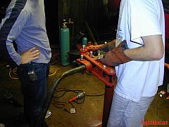
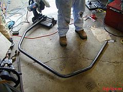
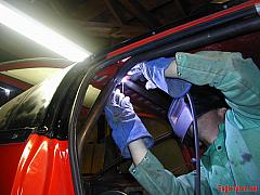
Over the past week, I can’t tell you how many small little updates, completions, fixes, and everything else that I’ve done to the car – It’s been quite insane. We’ve finished up the turbo mounting; fabbed up oil pickup tubes; painted things here and there; installed new parts; removed parts from the car; reinstalled parts again; modified everything; finished up details; puked oil, water, ATF and Gear oil on the ground; checked wiring; added pull-up resistors here and there; and the end result is this (An amazingly long post follows the video) :

So, this post needs quite a bit of explanation. Or, I should say that I *want* to explain more of it ๐Ÿ™‚ Last Sunday, the car started. It was around 5pm. In order to get that to happen, I had spent the previous week and a half getting things done after work, and on the previous weekend. Generally, I would work until around 11pm. It was quite an accomplishment. The sheer number of things done on the car, however small, all still had to happen before it could run.

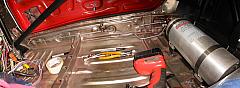
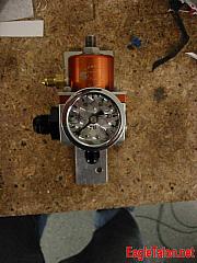
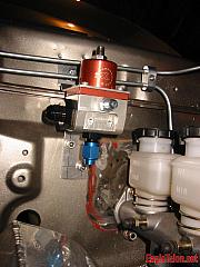
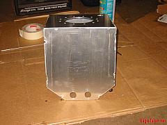
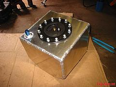
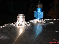
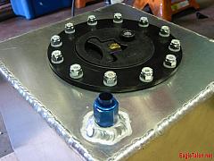
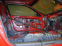
So, flashback to a few weeks ago. After getting the dash fabricated, welded up, fitted, sanded, painted, and to the point where I called it “done”, it was time to take it all back apart. I had to replace the Sport Comp fuel pressure gauge with a new phantom gauge so that they all looked identical – all except the AEM UEGO. After that, there was a fair amount of work to get all the plumbing done – all the plumbing on the car is AN, including the vacuum lines if you haven’t already noticed. So, it was kind of a clusterf*ck to get that all worked out. I also needed to get a fuel pressure isolator, and I was looking for one compatible with alcohol, in case I decide to run methanol, ethanol, or e85 in the future. And, for what it’s worth, you generally can’t find them. Malory makes one of them – it’s about $65. So I get the plumbing knocked out, and what’s next?

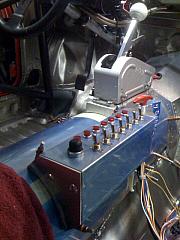
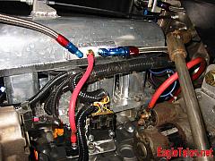
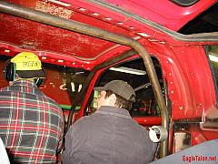
The gauge wiring harness. This thing was actually a lot more complicated than I thought it was going to be. The gauge harness actually a series of four harnesses: one for the AEM UEGO that connects to the o2 sensor, one for the lights (+12V switched on the switch panel,) one for the Tachometer & water temp gauge, and one for power to the AEM UEGO gauge and the EGT gauge. So, Why did I essentially make three harnesses? Well, the gauges need to be able to be *removed* from the dash, and without splitting the harness up, I would never be able to take the damn thing apart. The EGT gauge and the Tachometer have permanent wires coming out of the back of them, so they were good candidates for a base harness. the UEGO gauge has two connectors on the back of it – one with 6 wires going to the o2 sensor, and the other with four wires: power, ground, o-5V out and serial out. I ran the 0-5V out to the Haltech’s o2 input, so that I would be able to log voltage on the Haltech. Anyway, I took the UEGO’s power side harness, and merged it with the EGT harness, and used a 6 pin metripack connector to get all of those bundled into one harness. The other harness was similarly bundled: The water temp gauge has three spade connectors on the back of it, power, ground, and temperature sender. These were bundled with the Tachometer which also has permanently affixed wiring. to differentiate these, I used a 5 pin metripack connector. the last bundle was the lighting, and fortunately all the lighting is removable from the gauges that I have, so the lighting circuit was a much simpler circuit than it could have been ๐Ÿ˜ฎ Anyway, while doing that, I had remembered that I had no TACH signal, so I would have to run one from the factory power transistor back into the car to the gauge cluster. That was a pain to do, but only because it was time consuming. so yeah, no big deal, right? ๐Ÿ˜‰

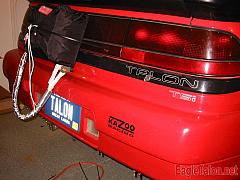
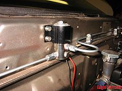
Next up on the list was hooking up the Fuel pump. I’m using an Aeromotive A1000 pump, but it hadn’t yet been wired in the back of the car. So, I broke out some connectors and wired it up to the battery shutoff switch. It was one of the simplest pieces of wiring on the car ๐Ÿ™‚ The pump is controlled through ground by the Haltech, and because I wanted to have some control over it, I ran a switched +12V signal to it. So, the Haltech has to be on and want to control it, and I have to allow the Haltech to control it. If I don’t, then computers may take over the world and all hell will break loose. In addition, the “rear wiring harness” (as I call it) also has a circuit for the lighting that runs to the center brake light in the wing. This will allow me to race at night ๐Ÿ™‚

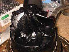
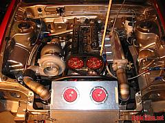
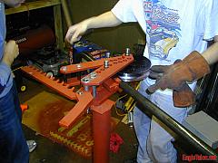
After the fuel pump was done, I started on the oil pump pickup. I already had a version that I was going to use, but it needed some adjustments because I had created it before deciding to go with a kiggly racing girdle on the car. After deciding to use the girdle, I had to shave the supports off of the pickup tube and remake them. So, Monday night rolled around and I pulled an old greasy block out of the shop. I threw it up on the engine stand, pulled it all apart, and fabbed up the brackets for the oil pickup tube.

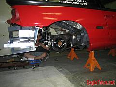
Tuesday night rolled around, and now it was time to get the oilpan installed. I put the newly fabbed oil pickup tube on the car, and then test fitted the oilpan on the greasy engine-stand 4g63. Everything was set. So, I RTV’d the new oilpan and the engine block. And then all hell broke loose. First, the stock pan bolts were too short to fit with the new oilpan’s flange, which is significantly thicker than a stock flange. No big deal, I have other bolts. So, I break them out and start bolting the oilpan to the car. Except I can’t bolt all the damn bolts to the car – some of the holes in the pan won’t lineup. Crap. Okay, now I have about 16 out of the 20 bolt holes all lines up, but I cannot get the holes on the front and back of the back to lineup, and I have to be careful because they bolt into aluminum ๐Ÿ˜ฎ So, I had to take the pan back off and cleanup *all* the RTV – off both the pan and the block. Then, I had to ream the oil pan bolt holes just slightly to get them to allow me to bolt them all up. But, it all bolted up to the mockup! Tolerances are a bitch sometimes. Anyway, got the holes reamed, and then did a complete test fit on the block under the car. All in all, I removed and replaced somewhere between sixty and eighty M6 cap head screws that night – not fun!

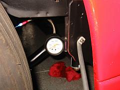
Wednesday rolled around and it was now time to get all the cooling system tightened and squared away. I started on the coolant neck – I pulled it off the car, made a restrictor plate to put between the head and neck, and then got all that RTV’d together. After that, I removed all the 12AN lines, and lubricated them before going through and getting them all tightened up. It wasn’t hard, but it was time consuming. After I was done with that, I pretty much called it a night, I think. If I didn’t, I just did other random stuff ;-p Oh, yeah, I ported the oil filter housing.

Thursday was my wife’s birthday. You can’t work on the project on your wife’s birthday.

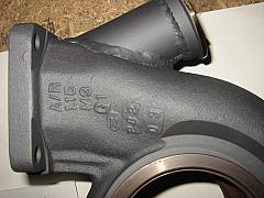
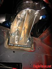
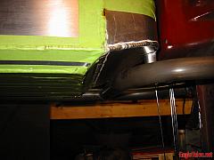
Friday was a day of complete random stuff. I don’t know what I did, but I spent most of it working. I think I finally got the turbo support bracket mounted to the car, among everything else. I also worked on the Haltech software on Friday, and found out something I didn’t want to know. The E6S, which is an older Haltech model, requires pullup resistors on the Ign Out and the Aux out 1 in order to be used with the stock power transistor units. I didn’t have these resistors in the car. Okay, to clarify, I didn’t *know* that these were required – the manual says nothing about them – but I found information that said that they were.

Saturday morning I spent the day running around – I went out and got a belt for the Alternator, new bolts for the oilpan that were 8mm longer (to allow room for lock washers,) and a few other things. Friday night I had already picked up oil, ATF, gear oil, a filter, distilled water, and some other things. By the time I got back, it was past 2:00, and Mark still wasn’t at the house. He finally got there, and we spent the rest of the night getting more stuff buttoned up. I replaced the oilpan bolts, and then we pulled apart the exhaust side of the engine apart. We had to reassemble it with gaskets. then, we put the flywheel on the car, which is an event in itself. We ended up working until about 10:30pm, and called it a night.

Sunday morning Mark got to the house around 11:00. I started working on the final maps for the Talon while Mark ate breakfast, and then we got to work. We started the day by getting the oil system all squared away – I put oil in the Talon, changed the oil filter, and pulled the timing belt off the car to prime the system. About 10 second into priming, oil started leaking out of the head where the stock oil feed bolt to the turbo goes. Oh crap – I completely forgot about that. So, Mark cut and fabbed up a bolt for me because we didn’t have anything short enough. It didn’t make too much of a mess, thankfully. Oil bolt plug in, we could now move on to the cooling system.

As I filling the cooling system, I started to go over all the connections in the system. Unfortunately, I forgot about two of them in the CSR water pump. The pump has two inlets and two outlets – I’m only using one of each. Because of that, I didn’t tighten the two plugs in the unused inlet and outlet. I discovered this when water started pouring out of the pump. Oops. Unfortunately, the plugs needed a 3/8″ hex wrench to tighen them, and I didn’t have one. I did, however, have a 3/8″ nut that I welded onto a bolt, and used that to tighten the whole mess. After that, the system was sealed ๐Ÿ™‚ Sealed so well, in fact, that we couldn’t get an air bubble out of it ๐Ÿ™ Damn! the not-so-quick fix we came to was simple. We jacked the front of the car up, pulled the jackstands out from underneath it, and lowered the front end of the car down to the ground. This gave us just movement of the cooling system to release the air bubble, and allow water to get to the water pump. Once we did that, I had to add the rest of almost two gallons of water. At this point, I have no clue how large the cooling system is, because I can’t tell you how much water we sopped up off the floor. I imagine it’s around a gallon and a half. Anyway, good riddance! That took *forever* to get done. Next on the list?

The Powerglide. The powerglide in the Talon is from Dave Buschur. I bought it off him back when he sold his tube car. So, it’s filled with previously used fluid. Getting the PG in the car was a pain, too. it’s difficult to lift, and I honestly should have just lifted the car up on the jackstands more than I did to get it in the car. Instead, I tried to lift it up while standing in the car. This was a mistake. I tilted the PG, and about 3 seconds later, ATF came pouring out the back of the transmission, all over the floor and under my shows. Argh. So, we cleaned that up (that’s three of three fluids on the floor for those of you who are counting) and then managed to get the PG in the car. Thankfully, I spent adequate time making sure that I didn’t get ATF all over the interior of the car.

While installing the PG, Rick showed up to lend a hand. I immediately put him on the laptop to check out the maps, and to compare them to a base map that I found. He spent the majority of the time working on that, but lent a hand when we needed tools or rags ๐Ÿ™‚

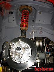
After the PG was installed, I continued working under the car by getting the transmission crossmember bolted in and getting the driveshaft installed. While I was doing this, Mark started filling the rear differential with gear oil. Right around this point, the fact that I only had a small set of hex wrenches bit us again. This time, Mark couldn’t get the fill plug out of the moser diff cover. So, he started fixing this issue by sanding down a 10mm nut, so that he’d be able to weld that to a bolt and be able to extract the plug using the method in which I installed the water pump plugs. Unfortunately, after welding that up for him, he broke it. Inside the diff plug! Argh! And, to make matters worse, he wasn’t able to get the nut out of the diff – it was completely smooth, and there was a ridge in the diff plug so he couldn’t get it out by any means ๐Ÿ™ So, I took my time under the car with a piece of tig filler rod and the mig welder. I mig’d the filler rod to the broken nut, and extracted it carefully. Mark got it really really stuck, and it was very hard to get it back out, but I was thankful that we didn’t make too big a mess. At that point, it was time to run up to the store and buy a proper hex wrench set. $8.99 solved that problem. I came back from the store, and filled the rear diff with fluid. It’s *large* – I put 2.5 quarts of cheap 70w140 into the rear diff. I used cheap fluid because the differential needs a break-in, and then I will drain and recycle the old fluid, and put some quality fluid in it’s place to replace it.

Ahh… Okay, now what? It was time to install the fuel system. This, fortunately, went without a hitch! How it that even possible? It’s not. Upon turning on the fuel system, I found that one of the lines that was previously tested was leaking. You don’t want fuel leaks in general, but because it was just weeping, we decided that we’d let it slide and fire the car anyway.

So, we verified that the fuel pump worked, the water pump worked, along with the fan. We then made sure the Haltech had the correct settings, and then plugged in the power transistors for the coils and the cam angle sensor. Then, we tried to fire it. It didn’t fire. We quickly discovered that the injectors were working by using a spare CAS to simulated the engine cranking. The Haltech saw RPM, so we knew that coils were the only issue. Right here, I remembered that the Haltech needed 1000ohm 1/4 watt resistors. Mark wanted me to show him the ignition schematic, so I whipped it up on paper for him. It would be a crime for me to get amnesia ๐Ÿ˜‰ Anyway, After I whipped it up, I grabbed a handful of resistors, and went soldering away. Sure enough, the car fired right up. But, it was only running on two cylinders. Okay… a quick wire check showed that I inadvertently wired the aux out 1 (the second coil trigger in this case) to the ground – I added a pull-down resistor instead of a pull-up resistor. I soldered a new resistor in place, and we fired it back up.

I would have loved to talk about how we got the map spot-fricking on and it purred like a kitten, but the fact of the matter is that wasn’t what happened. There was surge, and some sputtering at times, but nothing that we can’t tune. And actually, the car does start right up, but stumbles for a few seconds because I have to mess with the post start map – after about 10 second, it actually does run very well for just eyeballing a map out of it. It will get a whole lot better with one or two tuning sessions, but I didn’t want to make any of the neighbors angry ๐Ÿ˜‰

2007 – Random Progress Updates

Simpson 10-ft Skyjacker parachute

Simpson 10 foot Skyjacker chute, right at home.

CSR universal electric pump

CSR universal eletric water pump and custom mount

The front suspension, topped with a Wilwood drag brake kit.

The front suspension, topped with a Wilwood drag brake kit.

SX Fuel pressure regulator, with custom mount

SX Fuel pressure regulator, with custom mount

AN plumbing and wiring

A lot of plumbing and wiring, tucked under the intake manifold

Front hub and brake bracket assembly

Front hub and brake bracket assembly

Okay, so some of the things I’m going to talk about are a little bit overdue. First, I went around the car the other night and snapped a few pictures of things that I may have done a long time ago, but didn’t really cover very well, or that you’ve never seen a picture of. Anyway, the following are a bunch of pictures and explanations – click on a picture for a fullsize view:

A guy who lives here in Howell, Matt (One of the only active participants of the Eagletalon.net messageboard too ๐Ÿ˜‰ ,) mentioned that the back of the car looked a strange not having any taillights, and asked what I was planning on putting back there.

The plan has always been to put the stock taillights in the back of the car, and I even went as far as putting the rear end of the car together at one point in time. But for some reason, I had never taken a picture of it all together. So, there it is. ๐Ÿ™‚

I also hadn’t actually taken any pictures the water pump and water pump bracket. The water pump is in relatively the same spot as the stock factory aircan, if you can imagine that. It’s a CSR racing electic pump, mounted to an aluminum bracket that I wanted to make sure was nice and beefy. And, well, it is. I can stand on it. And it’s light. It’s amazing how strong you can make things. And actually, now that the water pump has power to it, the water pump bracket is probably way overkill, but I would rather have it be light, strong, and never have to worry about it. And It’s mounted to the framerail on a series of bolts that’ve been mounted in the framerail. You can see that I actually took a sheet of 1/8″ steel and welded that to the framerail. Again, this is probably all overkill, but it works well.

The other thing I haven’t really shot any pictures of is the front strut assembly. Now, the pictures that I have now aren’t the final version of the assembly – I actually have to replace the upper mount with a set of billet aluminum mounts that I got from Ty at RRE, and I also have a new set of Koni struts, and strut bodies that will be all cleaned up and on the car. Basically, all the rusty shit in the next picture will be replaced ๐Ÿ˜‰ In the background, you can see the -4AN turbo oil feed line, the -4AN oil pressure gauge line, and the -8AN turbo turbo line. You can also see the sweet ass header (ahh, modesty ;-p) Plus, the big cool damn Wilwood dynalite front brake kit.

The next item on the list is something I actually finished up this week. Tuesday night, I finally put together a drill press that I got for Christmas. I guess it was only a matter of time before my Dad wanted his borrowed drill press back, but it [i]was[/i] nice of him to get me one of my own for Christmas. this post isn’t about that though ๐Ÿ˜‰ It’s about what I did with it. I took my SX Fuel pressure regulator, and finally made it AN Compliant. The SX regulator, by default, has an 1/8″ barb on the side of is for the vacuum port. You hook that up to your intake manifold, and that’s the vacuum / boost reference. All the other holes machined into the FPR are either 1/8″ NPT or AN Port. And, my master plan is to have all the plumbing on the car to be AN – So, the FPR needed to be modified. I drilled out the 1/8″ barb, and tapped a 1/16″ NPT hole into it. I got a 1/16″ NPT to 4AN adapter fitting, and threaded it in. So now, it’s all set, and most of my plumbing is set. I still have to figure out the Wastegate setup, but almost all of the vacuum and oil pressure lines on the car are now AN.

And, this is the rats nest of a wiring harness. In this picture, you can see the bottom of the intake manifold, which is where all the plumbing and wiring for the engine is hidden. The wiring is okay – most of it has been tested, and all I need to do is find a way to mount it to the intake manifold – no big deal. The main trunk sort of has all these things coming off it. I’ve spent a lot of time making it as tidy as I felt I could. Anyway, you can also see the aluminum mounted on the side of the engine – that has the MAP sensor and the two mitsubishi power transistor units mounted to it. They’re wired into the Haltech harness, and determine when the COP ignition is fired. The car has two Power trasistor units because each unit contains two transistors – and instead of hooking them up in parallel, I wanted the coils to have their own ignitors. The “proper” way to do this is really to run a CDI ignition box, but I want to see if this can work because it’s a more simple solution. I guess we’ll see ๐Ÿ˜‰ In this picture, you can also see all the mad AN plumbing action, with the exception of the MAP sensor. It’s a standard GM 3 bar map, so it has a 1/4″ barb fitting on it, with no option of anything that I can convert to AN. So, until I upgrade to something like an AEM 3.5 bar sensor, this is just going to be the setup. I guess I can live with it. You’ll also see the 2 gauge wiring going to the starter. And, the alternator is also hooked up. I actually managed to use the stock alternator plug connector, and was able to remove and replace the stock spade connectors in it with new locking spade connectors that also work with my modular relays that I’m using in other areas of the car.

Ugh – okay, carpel-tunnel setting in ;-o Last but not least is a picture of the back of the front upright setup. About 14 months ago, we finished this project up, but aside from some pictures of the front uprights bare, I had never really posted a picture of the whole assembly. Well, here you can see it. The upright has the Chromoly kingpins, which is what the Wilwood brakes connect to. And, as you can see, the Wilwood has been all safety wired so that none of those Really Important brake bolts will come loose. Also, you can see the steering arm welded to the rest of the upright, along with the spacer underneath. All of these have been designed to minimize bump-steer, which is generally considered to be something somewhat misunderstood by a lot of people. Anyway, you can also see all the grade 8 hardware mounting the Wilwood caliper to the upright. And, of course, the 3AN teflon lined brake lines. “For offroad use only” ๐Ÿ™‚

Transmission Tunnel, Fuel Pressure Regulator and Line Lock

The results of some Aluminum, a little skill, and hours of work.

The results of some Aluminum, a little skill, and hours of work.

The line lock, mounted to the firewall

The line lock, mounted to the firewall

My SX fuel pressure regulator

My SX fuel pressure regulator – rivet-nutted to the firewall.

The new hood on the Talon

The new hood on the Talon

Over the last week or two Mark and I have been putting some work in on the Transmission tunnel on the Talon. While it would have been really easy to just place a box around the entire damn thing and call it done, we simply couldn’t do just that ๐Ÿ˜‰ So, we made a transmission tunnel that anyone who’s ever played StarFox would appreciate:

So, there you have it. The transmission tunnel is now done ๐Ÿ™‚ That’s a nice, refreshing accomplishment. All in all, I’d say we spent about 10 hours too long on making that. It’s okay, it looks damn cool.

In other car news: The Fuel pressure regulator has finally been mounted, too, along with the permanent mounting of the Line Lock / front brake line distribution block. This thing is actually really neat ๐Ÿ™‚

The line lock is simply a Summit Racing line lock kit, with some adapters. I mounted it to the firewall of the Talon using some rivet-nuts. If you’ve never seen these things and you’ve fabricated stuff, you’ve been under a rock, my friend ๐Ÿ˜‰ The rivet-nut is just that – it’s a nut that you stick in a hole, and then deform into place. The rivet-nut then stays in the hole, and provides a threaded hole for you to mount stuff to.

Because I wanted to use Stainless screws, I decided to use Zinc coated rivet-nuts. I contemplated aluminum rivet nuts, but I was concerned about corrosion. SS rivet-nuts are also available, but are ~5 times the price of the Zinc coated mild steel nuts, so I just got those instead. All in all, they are awesome. Go out and buy some. Right now. http://www.mcmaster.com ๐Ÿ˜‰

I also mounted the FPR, as I said before. Back in the day, somewhere around 1998, I purchased this SX Fuel pressure regulator from Buschur. Sure, the anodizing is a little faded, but it does it’s job, and does it well. So, I’m going to use it. Therefore, it needs to be mounted to the car. Sure, back in the day it hung off the fuel rail (how it never leaked, I’ll never know) and vibrated all over the place. Today though? Sorry, I know this car is going to shake when it’s together, so I focused on making a [b]solid[/b] mount for the regulator. Here’s the end result:

I am very happy with how it turned out – you can see I even broke the top mount so that it’d fit around the brake lines, and that body seam on the firewall. That’s the way to do it ๐Ÿ˜‰ So yeah, now that’s mounted.

Oh, and one last thing. In my last post I mentioned buying a hood off John Shepherd. Well, it’s fiberglass, and has the headlight covers integrated.

Four Inch Downpipe / Exhaust

A shot of the engine bay

A shot of the engine bay

The lower half of the exhaust, exiting under the car

The lower half of the exhaust, exiting under the car

Now THAT is an exhaust

Now THAT is an exhaust

Downpipe time! Over the weekend, we had a few visitors to the shop. More than any other weekend, anyway. Jim Craig and Kevin Kwiatkowski came out on Saturday to hang out, shoot the shit, return borrowed parts, and hang out for a bit. It was fun, but not the most productive weekend. Good times though ๐Ÿ™‚

Anyway, Mark and I got working on the complete 4″ exhaust system for the car. “complete” is kind of a relative term, because the entire exhaust system is roughly 48″ long. We purchased three 90 degree 1D stainless bends, 4 inch diameter and four feet of straight 4″ tubing to fabricate up the exhaust system. We got to work mocking up the downpipe, and then added two more bends to the system to get the exhaust to come out the side of the car. the result?

Now that is an exhaust ๐Ÿ™‚

Tin Work

The back of the car without a bumper.

The back of the car without a bumper.

The back of the car, complete with DZUS fasteners.

The back of the car, complete with DZUS fasteners.

The tin work was deceptive. It took a few months to get done, working on it some nights and on the weekends. I have a few shots of it here, but it was a bit more complicated than two pictures ๐Ÿ™‚

The Intercooler

The intercooler on the Talon was part of a larger project: The front end of the Talon. The cooling system, more specifically.

We pondered the cooling system. I wanted to do something on the DSM’s that nobody had done – ever. So, we came up with a plan. Instead of stacking everything like a cracker, and wedging it in the front of the car. I didn’t want to go as far as using a shifter cart radiator, and I also wanted to have a reasonbly decent sized IC core, filled with ice and water. So, how would be able to accomplish that? Well, we mounted the radiator and IC horizontally, instead of vertically. Alright, well, the radiator isn’t horizontal, it’s about 30 degrees from horizontal, but it makes more room for the air:water IC that we would up using.

The premise of the intercooler is reasonably simple. Instead of running lines, a high volume pump, and end up with the same effect at the end of the day, the concept is this: Use the mass of the aluminum intercooler along with the ice and water to take the heat of the charge from the turbo throughout the run. It’s complicated to explain, but quite simple when you see it. The core contains an integrated water tank.

Okay, so now that that’s explained – how did we make the IC? Well, Mark pulled up some specs, and through a thermal dissipation formula he used to come up with figures for his air:water intercooler, figured it’d take about 15 pounds of ice to cool the charge we wanted to chill, for one pass ๐Ÿ˜ฎ So, we got to work. We called up Bell Intercoolers and ordered up a core. Then Mark hand bent up a bunch of 1/8″ 6061 for some end tanks, and some .090″ 6061 for the IC ice tank.

Through a friend, Tom Shwalm, we were able to gain access to a welder that is a little bigger than my little TIG to weld up the core. It was cake; we spent a day out at VT Competition Engine Development in Lansing, Michigan working on the Intercooler, and getting the new block honed. The honing was the easy part; we didn’t have to do that ๐Ÿ˜‰ I didn’t actually use VT to complete the IC, but I did use VT’s Lincoln to weld up the end-tanks, and to weld the tanks to the core. There is a lot of thermal mass in the 30 pound core, so I wanted to make sure that we’d have enough amperage to get the job done. Plus, it was really a lot of fun to hang out with those guys. It’s sad to say that VT doesn’t exist quite in the form that it did back in early 2004, but VT Engines, Inc is still in business.

Here’s the scoop for those who don’t know: VT Competition Engine Development was purchased by a guy named Chris (I don’t remember Chris’s name off the top of my head) – anyway, Chris purchased VT, and changed it’s name to VT Engines, Inc. The old owners moved out, and the new owner took up shop. I’d still recommend going to those guys for Ford mod motor work – Their engine builders kick ass ๐Ÿ™‚ Unfortunately for us, they now focus primarily on Ford 4.6 and 5.4 mod engines.

Anyway, back to the IC, right? So, we got the IC finished enough, and then mounted it to the car. We used 1-1/4″ chromoly tubing to mount the IC right in front of the engine. Unlike any other DSM ๐Ÿ™‚

Fuel Cell

The parts of the fuel cell, all tacked together

The parts of the fuel cell, all tacked together

The fuel cell, welded

The fuel cell, welded

-8AN bungs on the fuel cell

Bungs on the fuel cell

Filler cap, return line

The filler cap and return line on the fuel cell.

The Fuel cell in the Talon was a relatively quick and easy item to get all squared away. While Mark and I were building the Intake manifold, I had some time to kill. I had ordered some random AN bungs, and a fuel cell sealed cap from Summit.

While Mark machined up the intake manifold flange over the fourth of July weekend, I spent time in the shop measuring and cutting a sheet of 6061 T6. Once I figured out the shape, and the size of the tank, and the sump, I went to work meauring and cutting up a bunch of aluminum. We ended up doing this out at Mark’s work.

It wasn’t until we got back to the shop that I welded up the aluminum cell. With the math, the cell was approximately just over 3 gallons. We confirmed that once we welded the cell up completely. The bungs went on the tank, along with the cap, and we started measuring. Using water, and a graduated container, we actually got more than three gallons out of the cell – it’s around 3.2 gallons.

The next step to the tank was mounting it in the car. This was a little more tricky than normal. Because of the way the cell was mounted between the framerails with nothing to protect it, NHRA required a 1-1/4″ by .063″ wall cage be mouted around the fuel cell. So, we built a cage that’d mount the cell, and the fuel pump (to be replaced later by twin pumps – more on that in the future) All in all, it turned out great ๐Ÿ™‚

Chromoly Rollcage Construction

Driving to Silver Lake, MI

Lake Michigan

Chromoly Steel Tubing

4130 Chromoly tubing, all loaded up and ready to go

Model3 Tubing Bender

The model 3 tubing bender in action

repositioning the tube

Repositioning the tube for another test bend.

Chopsaw Main Hoop

Chopping the main hoop.

The Drivers side door bard and a-pillar

The Drivers side door bard and a-pillar

Tacking the main hoop

Mark’s favorite pictures involve me welding something.

Mark and Rick hanging out inside the car

Mark and Rick hanging out inside the car

To tell you the truth, the roll cage in the Talon took a whole lot longer than expected. There were weeks of literally nothing happening because we spent a whole lot of time aquiring parts and tools. I wasn’t completely opposed to buying apre bent roll cage kit, I just didn’t end up finding one that I liked. So, the option of making my own roll cage cameabout as a neat idea, so I started looking into tubing benders. I made the mistake that a lot of other people make. I went out, and purchased a cheap ~$125 bow and arrow type pie bender. At the time, I didn’t think anything of it – I figured it would work just fine. Let me tell you a little bit about those types of benders: There’s a main die, with two other dies that work by cramming the main die through the smaller two die, making the schedule 40 pipe bend. This method does not work with what is considered thin-wall tubing. NHRA required .125″ mild steel, or .083″ chromoly tubing is way to thin for this type of bender. What does it do? It wrinkles the hell out of the tube, that’s what it does ๐Ÿ˜ฎ Well, this wasn’t found out until I already obtained the tubing. Chassis Shop is down the road from my house. And, by down the road, I mean 120 miles away, in scenic Mears Michigan, right next to Silver Lake Michigan. Right next to lake Michigan. It’s a beautiful facility filled with all the chromoly and just about any other type of raw material needed to make a dragster, a dune buggy, an off-road vehicle, or just about anything else. While I didn’t exactly get the grand tour, I did just stop by a few days after placing an order for about 500 feet of chromoly total. I could be off by a few hundred feet – I can’t remember anymore. In any case, I did get to see the back room, and run around the aisles a little bit. *sigh* If I only had $100,000 to spend in that place ๐Ÿ˜‰ So, anyway, back to the story, right? Getting back to the shop with a bunch of chromoly was fun. We got back, and chucked up some old mild steel that was once a roll cage for the Talon, and wrinkled the absolute piss out of it. This brand new chromoly was thinner wall, so it would have been even worse with wrinkling. Shit. What would we do? Well, looking into it some more, the type of bender we’d require would be more like a mandrel with a follow bar that helped the tube bend more as it bent. Also, something with a reasonably sized diameter for the die, so that the resulting radius would be larger so that the pipe wouldn’t bend. Well, shit, there’s no reason to go out and get all this chromoly, and half-ass this cage. So, I went out and bought the proper setup, a Model 3 tubing bender. This thing is bad ass ๐Ÿ™‚ Now with the tubing bender, we were able to create whatever we wanted to. So, we started off with the main hoop. Cake, right? Okay, now onto the halo and A-pillar bars. These were tough. I wanted this stuff to look nice, tightly follow the stock factory body, and look fucking sweet. We accomplished all of this. The halo wasn’t any fun at all, but it turned out nicely. ๐Ÿ™‚ Also, since I’m young and relatively agile, I opted for the 1.5″ X-bars instead of a single bar for the sidebars. Basically, all you need to do is check out the pictures. ๐Ÿ™‚ They explain it all.